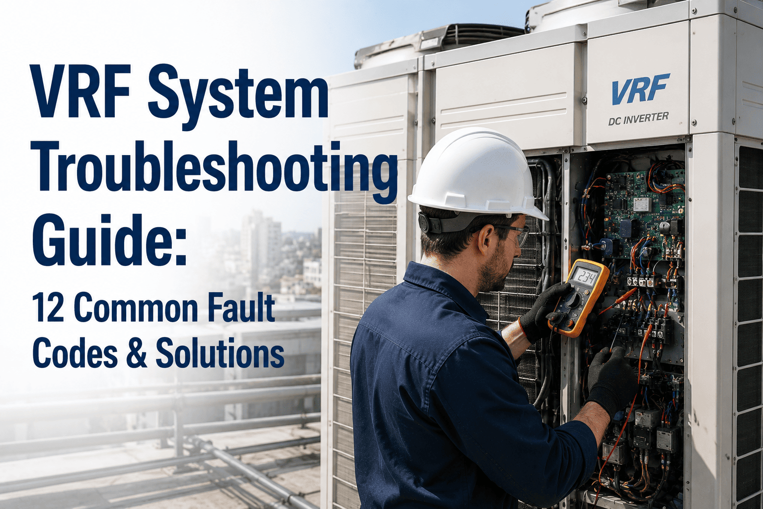
A VRF system is one of the most intelligent HVAC architectures in commercial buildings — and one of the most difficult to diagnose when something goes wrong. Unlike a conventional split system where a fault is isolated to one unit, variable refrigerant flow systems distribute faults across a network of interconnected indoor and outdoor units. A communication error on one indoor head can mask a refrigerant imbalance across twelve zones. A single faulty sensor can prevent an entire building from cooling. This guide covers 12 of the most common VRF fault codes, what they mean across Mitsubishi, Daikin, LG, Samsung, and Carrier platforms, and the diagnostic steps that resolve each fault before it escalates. Sign up free to log your VRF fault history in Oxmaint from day one, or book a demo to see how facilities teams manage multi-unit VRF portfolios from a single dashboard.
One fault. One unit. Clear symptom. Isolated repair. Fault code points directly to the failed component in most cases.
One fault code can appear on multiple indoor units caused by one outdoor unit fault. Refrigerant circuit imbalance affects all zones. Communication errors cascade. Root cause and symptom are rarely in the same unit.
12 Common VRF Fault Codes — Causes, Diagnosis and Solutions
Loss of signal on the 2-wire or 3-wire communication bus between one or more indoor units and the outdoor unit. Loose terminal connections, damaged shielded cable, incorrect address settings on a new or replaced indoor unit, or electrical interference near the communication wiring.
Check communication wiring at both the indoor and outdoor unit terminals — terminals loosen from vibration over time. Verify address settings on the affected indoor unit match the system configuration. Test cable continuity and check for ground fault on communication bus. Inspect for parallel runs with high-voltage cabling causing interference.
Re-seat all communication terminals at outdoor PCB and at affected indoor unit. Correct address configuration. Replace damaged cable section. If fault persists after wiring confirmed good — suspect indoor PCB or outdoor PCB communication module failure. Log the fault event and resolution in your CMMS to detect recurrence.
Two or more indoor units configured with the same address on the communication bus. Almost exclusively triggered after a unit replacement or a new installation where address assignment was not verified. System cannot differentiate between units sharing an address — both stop responding correctly.
Access address configuration on each indoor unit via wired remote or PCB DIP switch. List all assigned addresses against the system configuration diagram. Any duplicate will confirm this fault. Common after replacement of a failed indoor PCB where the replacement board comes factory-set to address 00.
Reassign unique addresses to the conflicting units following manufacturer sequence. Power cycle affected units after address correction. Update your CMMS asset record for each indoor unit with its confirmed address number — so the next replacement technician can configure correctly without guessing.
Discharge pressure exceeds the high pressure cutout threshold — typically 600–650 psig on R-410A systems. Caused by dirty or blocked condenser coil, failed condenser fan motor, refrigerant overcharge, restricted liquid line, or non-condensables in the refrigerant circuit.
Inspect condenser coil for fouling and airflow obstruction. Verify all condenser fans are operating. Connect manifold gauges — high discharge with normal suction indicates condenser-side restriction. Abnormally high both sides may indicate overcharge or non-condensables. Check ambient temperature against manufacturer operating limits.
Clean condenser coil if fouled. Repair or replace failed condenser fan. If refrigerant overcharge confirmed — recover and recharge to spec. Do not simply reset and restart without identifying cause — a high pressure trip that recurs within 24 hours indicates an unresolved mechanical condition, not a nuisance trip. Book a demo to see how Oxmaint tracks high-pressure fault recurrence patterns across your VRF fleet.
Suction pressure drops below the low pressure cutout threshold. Primary cause is refrigerant leak. Secondary causes include blocked or clogged indoor unit filters reducing evaporator airflow, frozen evaporator coil, or a failed expansion valve restricting refrigerant flow to indoor units.
Check all indoor unit filters — severely restricted airflow causes low pressure that is commonly misdiagnosed as a refrigerant leak. Inspect indoor units for frozen coils. Connect gauges and compare suction pressure to manufacturer P-T charts. If low with no obvious airflow restriction — pressure test for refrigerant leak.
Clean or replace blocked filters. Defrost frozen coils and identify the underlying cause of icing. Locate and repair refrigerant leak before recharging — recharging without finding the leak produces a repeat fault within weeks. Document refrigerant charge baseline in CMMS to track loss rate over time.
Electronic expansion valve fails to open, close, or modulate correctly. EEV faults cause refrigerant starvation to affected indoor units or flooding that results in liquid refrigerant reaching the compressor. Causes include failed stepper motor coil, blocked valve body from contamination, or EEV driver board failure.
Listen for EEV stepper motor clicking during startup — silence when stepping should be heard indicates motor failure. Check EEV coil resistance — out-of-spec resistance confirms coil failure. Verify 12V DC supply to EEV driver. Compare superheat readings at affected indoor unit to expected values — abnormal superheat confirms valve fault.
Replace EEV coil or full valve assembly as required. Flush refrigerant circuit if contamination caused blockage. Recalibrate EEV position after replacement following manufacturer procedure — uncalibrated EEV produces superheat errors that appear as sensor faults and generate additional fault codes.
Oxmaint tracks fault code history, maintenance records, and refrigerant charge data for every VRF unit — so your team stops diagnosing the same fault twice. Sign up free or book a demo to see the VRF portfolio dashboard.
Compressor drawing current above its rated threshold. Caused by mechanical wear increasing internal friction, liquid slugging from refrigerant flooding the compressor, operation under abnormal pressure conditions, or early-stage compressor winding failure. Also triggered by inverter board faults sending incorrect frequency commands.
Measure compressor amperage at each phase against nameplate FLA. Compare system pressures to normal operating range — abnormal pressures cause abnormal amperage. Check inverter board output frequency and voltage. If amperage elevated with normal pressures — compressor mechanical condition is degrading. Review fault history for prior low or high pressure events that may have caused damage.
Correct any refrigerant circuit condition before restarting. Replace inverter board if faulty output confirmed. If mechanical compressor failure — compressor replacement required. This fault is frequently preceded by repeated low pressure trips — log fault history chronologically in CMMS to identify the root cause chain before authorizing compressor replacement.
Inverter module temperature exceeds safe operating threshold. Primary causes are blocked or degraded inverter heatsink cooling, outdoor unit placed in a location with insufficient ventilation clearance, dirty condenser coil causing elevated ambient temperature around the outdoor PCB, or failed cooling fan for the inverter section.
Inspect outdoor unit clearances against installation specification — minimum clearances are frequently violated after equipment is installed around units over time. Check inverter heatsink and clean if dust-fouled. Verify inverter section cooling fan is spinning. Measure outdoor ambient temperature — units operating above rated ambient will trigger this fault intermittently on peak summer days.
Clean inverter heatsink and replace cooling fan if failed. Restore minimum clearances if obstructed. If fault occurs only on extreme heat days and clearances are correct — verify outdoor ambient rating against local summer peak conditions. Document outdoor unit installation clearances in CMMS asset record for reference at every future PM visit.
Room temperature thermistor reading outside the valid range — typically open circuit (disconnected) or short circuit (shorted leads). Causes include age-related thermistor resistance drift, physical damage to sensor leads from cleaning activity, or moisture ingress into indoor unit PCB corrupting sensor input.
Measure thermistor resistance at the PCB connector and compare to the manufacturer resistance-temperature curve. An open circuit reads very high resistance; a short reads near zero. Verify sensor connector is seated correctly on PCB — loose connectors produce intermittent faults that are difficult to reproduce during a service visit.
Replace faulty thermistor. Reseat connector if loose. If PCB moisture damage is found — PCB replacement required after identifying and sealing the moisture ingress point. Log thermistor replacement in CMMS with the resistance reading found at fault — useful baseline for future comparison on the same unit.
The discharge pipe temperature sensor — which monitors compressor discharge line temperature as a primary compressor protection input — reads out of range. This is a critical sensor because the VRF controller uses it to limit compressor speed and protect against overheating. A failed sensor causes the system to default to limited capacity or shut down entirely.
Measure discharge sensor resistance at outdoor PCB and compare to P-T curve for your refrigerant type. Verify sensor is clamped correctly to the discharge line — a sensor that has vibrated loose will read ambient temperature rather than discharge line temperature, producing an apparently normal reading that masks the actual fault.
Replace discharge temperature sensor. Ensure new sensor is correctly clamped with thermally conductive compound and insulation wrap as specified. This is a frequently missed PM check — add discharge sensor resistance measurement to annual outdoor unit PM checklist in Oxmaint to detect drift before a fault code is triggered.
Indoor unit fan motor fails to reach commanded speed or stops entirely. Causes include motor winding failure, failed motor driver on indoor PCB, foreign object obstructing fan scroll or blade, or bearing failure producing mechanical resistance that the motor cannot overcome at normal operating current.
Inspect fan scroll for debris obstruction — ceiling cassette units accumulate significant debris on the fan blade over time. Spin fan manually — resistance or roughness indicates bearing failure. Measure motor winding resistance and compare to spec. Check motor driver output voltage from indoor PCB.
Clear any obstruction. Replace motor if bearing or winding failure confirmed. Replace indoor PCB if motor driver output fault confirmed with a known-good motor. Fan blade cleaning should be part of the annual indoor unit PM to prevent debris accumulation reaching fault-trigger levels. Sign up to schedule fan cleaning PMs across all indoor units in your portfolio.
Condensate float switch detects overflow condition in the indoor unit drain pan. Causes include blocked drain line from algae or debris, failed condensate pump on units where gravity drainage is not possible, or a unit that has shifted from level over time causing the pan to drain toward the blocked end.
Inspect drain pan — if full or nearly full, confirms float switch activation is genuine (not a false trigger from a stuck switch). Flush drain line with condensate tabs or dilute bleach solution. Test condensate pump operation if installed. Check unit levelness — ceiling cassette units shift over time as ceiling infrastructure moves.
Clear drain line and verify free flow before restarting. Replace condensate pump if failed. Re-level unit if required. Annual drain flush should be a scheduled PM task for every indoor VRF unit — the cost of a missed drain cleaning is a water damage claim against the ceiling, not a repair invoice.
PCB self-diagnostics detect an internal processing or memory fault. Causes include power surge or lightning strike, moisture ingress, capacitor aging on older boards, or EEPROM data corruption from an interrupted firmware update. Outdoor PCB failures typically affect all zones simultaneously — indoor PCB failures affect only that unit's zone.
Retrieve all stored fault codes before any power cycling — power cycling clears the fault log on many platforms. Verify all input voltages to the PCB are correct. Confirm all sensors connected to the board read within normal ranges — a sensor fault can be misread as a PCB fault on some platforms. If inputs correct and board still faults — PCB failure confirmed.
Replace PCB. For outdoor unit PCB replacement — configuration data must be re-entered, including indoor unit count, system capacity, and refrigerant type. For indoor unit PCB — address must be reassigned. Log PCB replacement event in CMMS with serial numbers of old and new boards — warranty and recurring failure tracking requires this record. Book a demo to see how Oxmaint manages PCB replacement history across your VRF portfolio.
VRF Fault Code Quick-Reference by Brand
| Fault Type | Mitsubishi | Daikin | LG | Samsung | Carrier |
|---|---|---|---|---|---|
| Indoor-Outdoor Communication | E1 / U4 | U4 / UF | Ch01 | E101 | E1 |
| High Pressure Trip | E3 | E3 | Ch03 | E401 | P4 |
| Low Pressure Trip | E4 | E4 | Ch04 | E402 | F0 |
| EEV / Expansion Valve | E5 / 2502 | E5 | Ch05 | E501 | — |
| Compressor Overcurrent | E6 | E6 | Ch06 | E601 | E2 |
| Inverter Overheat | P4 | U2 / L5 | Ch07 | E701 | P4 |
| Room Temp Sensor | E7 | E7 | Ch08 | E301 | — |
| Discharge Temp Sensor | E8 | E9 | — | E307 | F3 |
| Indoor Fan Motor | E1 | E1 | Ch10 | E201 | — |
| Condensate Float Switch | E9 | A3 | Ch12 | E801 | — |
| PCB / Control Board | E0 / F8 | U0 / L4 | — | E601 | F8 |
| Address Conflict | E6 | U5 | — | E201 | C1 |
VRF Preventive Maintenance Schedule
Inspect and clean or replace indoor unit filters. Clogged filters are the single most common cause of low pressure trips and evaporator coil icing in VRF systems. High-occupancy zones require monthly checks.
Flush all indoor unit drain lines with condensate treatment solution. Test condensate pump operation. VRF indoor units in humid climates block faster than quarterly — adjust interval based on local conditions.
Clean indoor unit evaporator coils and fan blades. Clean outdoor unit condenser coils. Dirty condenser coils directly cause high pressure trips and inverter overheating in summer — spring cleaning is non-negotiable.
Inspect all communication wiring terminals and re-torque. Test all thermistor resistances against P-T curves. Check capacitor values. Measure refrigerant pressure against charge baseline. Review fault log history for the preceding 12 months.
Stop Diagnosing the Same VRF Fault Twice
Oxmaint logs every fault code, every corrective action, and every PM completion across your entire VRF portfolio — indoor units, outdoor units, and communication networks. When a fault recurs, the full history is there in seconds. When a PM is missed, an escalation fires automatically. Sign up free or book a demo to see the platform in action for your VRF fleet.