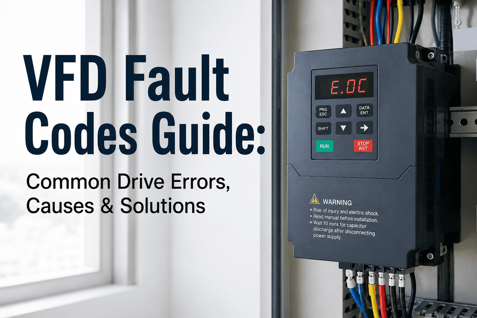
A VFD fault code is not a nuisance — it is a protected shutdown with a reason attached. When a variable frequency drive trips, it does not guess. It measured something beyond its safe operating threshold, stopped the motor to prevent damage, and left a code on the display. What happens next determines whether you lose two hours or two weeks. Most facilities reset the fault, restart the motor, and move on — until the drive does not come back up at all. Start a free trial to see how Oxmaint tracks VFD fault history, links recurring codes to root causes, and converts fault patterns into scheduled corrective actions before drives fail.
80%
Of VFD faults trace back to just five root cause categories — power quality, cooling, wiring, parameters, or mechanical load
7
Most common fault types covered in this guide — each with root causes and field-proven diagnostic steps
3x
Higher repeat fault rate in facilities without digital fault history tracking in a CMMS
$0
Cost of catching a fault pattern early — versus thousands in unplanned compressor or drive replacement
What You Will Learn
This guide explains how VFD fault codes work, walks through the 7 most common fault types with their causes and diagnostic steps, gives you a universal troubleshooting sequence that works across brands, covers the PM tasks that prevent most faults from happening, and explains why fault history in a CMMS is the difference between fixing a drive and understanding it.
How VFD Fault Codes Work
Every VFD continuously monitors operating parameters — output current, DC bus voltage, drive temperature, input phase balance, motor feedback signals, and more. When any measured value crosses a configured threshold, the drive trips: it stops the output to the motor, logs an internal fault record, and displays a code. That code is the drive's diagnosis, not a random number. The fault naming conventions differ between manufacturers — Siemens uses F-codes, ABB uses fault numbers, Yaskawa uses OC/OV/OH abbreviations — but the underlying fault categories are universal across all major brands.
Always Record the Code Before Resetting
Many drives store a fault log in memory — but it can be overwritten by new faults or cleared on reset. The fault code displayed at the moment of trip is the most specific diagnostic information you have. Note the code, the time, the ambient conditions, and what the drive was doing when it faulted. Resetting without recording discards the best clue you have.
Faults vs Alarms vs Warnings
Most drives distinguish between faults (trip — motor stops, must be reset), alarms (drive continues but condition is flagged), and warnings (informational — operating near a limit). Alarms and warnings are where prevention happens. A drive running in alarm state for days before it faults is not an unusual event — it is a preventable failure that was ignored at every earlier stage.
The 7 Most Common VFD Fault Types
Regardless of manufacturer, these seven fault categories account for the overwhelming majority of field VFD trips. Each has a distinct set of causes and a clear diagnostic path. Sign up to Oxmaint to track every fault code against your VFD assets — so patterns become visible before they become failures.
OC
Overcurrent Fault
Most frequently occurring VFD fault across all applications
An overcurrent fault fires when the drive detects output current exceeding its rated limit. The drive trips instantly to protect its output transistors (IGBTs) and the motor windings. Overcurrent is the broadest fault category — it can originate in the drive, the cable, or the mechanical load.
Common Causes
Acceleration ramp too short for load inertia, mechanical binding or jammed equipment, motor cable phase-to-phase short, motor insulation failure, drive undersized for load, loose output terminal connections
Brand Code Examples
Siemens: F30001 — ABB: Fault 2310 — Yaskawa: oC — Allen-Bradley: F002 — Danfoss: OC Trip
Diagnostic Steps
Decouple the load and megger the motor to confirm insulation health. Check motor cable for damage. Verify acceleration/deceleration ramp times — extend if tripping at start. Confirm motor nameplate data matches drive parameters. Check for mechanical binding in the driven equipment before restarting.
OV
Overvoltage Fault
DC bus voltage exceeds safe limit — common during deceleration
An overvoltage fault occurs when the DC bus voltage rises above the drive's safe threshold. On a 480V system, the DC bus normally operates around 650–680V DC. During rapid deceleration, the motor acts as a generator — feeding energy back into the DC bus. Without a way to absorb this energy, bus voltage climbs until the drive trips. Supply spikes from the utility can also trigger overvoltage independently of the load.
Common Causes
Deceleration ramp too fast for high-inertia load, regenerative load without braking resistor, utility voltage spikes or transients, motor driving the load (crane, conveyor overhauling)
Brand Code Examples
Siemens: F30002 — ABB: Fault 3210 — Yaskawa: oV — Allen-Bradley: F004 — Danfoss: OV Trip
Diagnostic Steps
Extend deceleration ramp time (parameter p1121 on Siemens, equivalent on other brands). For high-inertia loads, install a braking resistor to dissipate regenerative energy. Verify incoming supply voltage is within ±10% of nameplate. Enable the DC bus voltage controller if available in drive parameters.
UV
Undervoltage Fault
Supply sag or phase loss — often a symptom of an upstream problem
An undervoltage fault fires when DC bus voltage drops below the minimum threshold. The drive cannot produce correct output voltage to the motor and trips to prevent torque instability and motor overheating. Undervoltage rarely originates inside the drive — the cause is almost always upstream. A weak supply, single-phasing, shared circuits with large inrush loads, or failed input fuses are the most common culprits.
Common Causes
Utility voltage sags, single-phase loss on three-phase supply, blown input fuse, shared circuit with large motor starting, inadequate conductor sizing, generator supply with poor regulation
Brand Code Examples
Siemens: F30003 — ABB: Fault 3130 — Yaskawa: UV — Allen-Bradley: F003 — Danfoss: UV Trip
Diagnostic Steps
Verify three-phase input voltage at the drive terminals under load — use a true RMS meter. Check all three input fuses. Confirm line-to-line voltages are balanced within a few percent. If undervoltage correlates with other equipment starting, investigate supply capacity and dedicated circuit sizing.
OH
Overtemperature Fault
Drive or motor heat — blocked airflow is the leading cause
Overtemperature trips protect the drive's power electronics — particularly the IGBT modules — from thermal damage. The drive's internal heatsink temperature is monitored continuously. Intermittent overtemperature faults that correlate with summer afternoons almost always indicate a marginal cooling situation: the system runs fine in cooler conditions but crosses the thermal threshold on hot days. That pattern is the drive warning you to act before summer becomes a failure.
Common Causes
Blocked or failed cooling fan, dust-clogged heatsink fins, high ambient temperature in enclosure, drive undersized for continuous duty, inadequate enclosure ventilation, enclosure in direct sunlight
Brand Code Examples
Siemens: F30004 — ABB: Fault 4110 — Yaskawa: OH — Allen-Bradley: F010 — Danfoss: OT Trip
Diagnostic Steps
Verify cooling fan is spinning and moving air — replace if noisy or seized. Clean heatsink fins with dry compressed air. Measure enclosure ambient temperature and compare to drive spec (typically 40–50°C max). Review drive installation spacing requirements — minimum clearances on all sides are mandatory, not guidelines.
GF
Ground Fault
Unintended path to ground — safety and insulation failure indicator
A ground fault indicates current flowing from a conductor to ground outside the designed path. This is both a safety event and an insulation failure indicator. Intermittent ground faults that correlate with rain or high humidity point to moisture ingress in conduit, motor terminal box, or cable. A flooded conduit often starts as an overcurrent problem before transitioning to a full ground fault trip — the progression is the diagnostic pattern.
Common Causes
Motor winding insulation failure, damaged cable insulation from abrasion or rodents, moisture in motor terminal box or conduit, loose ground connections, cable routed too close to hot surfaces
Brand Code Examples
Siemens: F30021 — ABB: Fault 2330 — Yaskawa: GF — Allen-Bradley: F013 — Danfoss: GF Trip
Diagnostic Steps
Megger the motor at 500V or 1000V DC — insulation resistance below 1 MΩ indicates motor winding failure. Inspect motor cable for physical damage along its entire run. Check terminal box for moisture or corrosion. If moisture is suspected in the motor, some drives support a motor drying function (DC injection at low current) — consult manufacturer documentation.
OL
Motor Overload Fault
Sustained high current — thermal model tracks cumulative heat
Unlike an overcurrent trip (which is instantaneous), a motor overload fault uses an internal thermal model. The drive accumulates current-time data and trips when the model indicates the motor has absorbed more heat than it can safely dissipate. This protects motors that are running above rated current continuously — even if the current level would not trigger an instant overcurrent trip. At low VFD-controlled speeds, motor cooling fans slow down, reducing heat dissipation and making the motor more vulnerable to overload.
Common Causes
Process load exceeding motor rating, sustained low-speed operation reducing motor cooling, incorrect motor full-load amps entered in parameters, worn bearings adding friction, degraded motor insulation increasing losses
Brand Code Examples
Siemens: F07900 — ABB: Fault 7121 — Yaskawa: oL1 — Allen-Bradley: F007 — Danfoss: Motor OL
Diagnostic Steps
Verify motor FLA parameter matches nameplate. Measure actual output current and compare to motor rated current. Check motor nameplate duty rating — standard motors running at low speed continuously on VFD require an auxiliary cooling fan or an inverter-duty rated motor. Review process load for changes since last baseline measurement.
CE
Communication / Input Phase Loss Fault
Signal loss or phase imbalance — often intermittent and misdiagnosed
Communication faults occur when the drive loses its control signal — whether from a BAS, PLC, or building management system. Input phase loss faults fire when the drive detects unequal current draw on its three input phases, indicating one phase has weakened or dropped. Both fault types are frequently intermittent and the hardest to diagnose without data logging, because they can clear on their own and leave no physical evidence behind.
Common Causes
Loose control wiring at drive terminals, BAS or PLC interlock open, incorrect HOA switch position, failing input contactor, corroded terminal connections, utility phase imbalance, blown input fuse on one phase
Brand Code Examples
Siemens: F07080 — ABB: Fault 3130 — Yaskawa: CPF — Allen-Bradley: F029 — Danfoss: Loss of Com
Diagnostic Steps
Confirm a run command actually reaches the drive — check HOA switch position, PLC interlock status, and control terminal voltage before assuming a drive fault. Measure input line-to-line voltages on all three phases under load. Check communication cable routing for proximity to power cables that cause signal interference.
Your VFD Already Knows What's Wrong. Does Your CMMS?
Oxmaint captures every fault code against the right VFD asset, links repeated codes into visible patterns, and auto-generates corrective action work orders — so your team acts on the fault history, not the memory of the technician who last touched the drive. Sign up free or book a demo to see VFD asset intelligence live.
Universal VFD Troubleshooting Sequence
This sequence works across manufacturers. Use it before replacing any component — most field VFD calls do not require parts, they require systematic elimination.
Step 1
Record Before Resetting
Note the exact fault code, time of fault, ambient conditions, and what the drive was doing — acceleration, running at speed, deceleration, or idle. Access the fault log in the drive menu before resetting. This information is the diagnostic foundation — do not discard it.
Step 2
Verify Input Power
Measure line-to-line input voltages under load with a true RMS meter. Check all three phases for balance — more than a few percent difference indicates a supply problem. On 480V systems, verify DC bus reads approximately 650–680V DC. Supply issues cause a wide range of seemingly unrelated fault codes.
Step 3
Confirm Run Command Exists
Verify a run command actually reaches the drive before assuming internal fault. Check HOA switch position, PLC interlock status, and control terminal voltage. Many field service calls have been resolved by finding the HOA switch in an unexpected position — the drive was never commanded to run.
Step 4
Isolate the Load
Decouple the mechanical load where safe to do so and attempt to run the motor uncoupled. If the fault clears, the problem is mechanical — binding, jammed equipment, or excessive load inertia. If the fault persists without the load, the problem is electrical — in the drive, cable, or motor.
Step 5
Test Motor and Cable
Megger the motor at 500V or 1000V DC — insulation resistance should read above 1 MΩ. Inspect motor cable for physical damage, especially at conduit entry points and inside the terminal box. Check for moisture at any enclosure. A motor that passes a megger test but still faults may have marginal insulation that fails under operating voltage.
Step 6
Verify Parameters
Confirm motor nameplate data is entered correctly — rated voltage, rated current, rated frequency, and motor type. Incorrect parameters cause the drive to operate with wrong protection thresholds. Review acceleration and deceleration ramp times against load inertia. Parameters that were correct at commissioning may no longer match after motor or load changes.
VFD Preventive Maintenance: What Prevents Most Faults
Most VFD faults are not random — they are the result of deferred maintenance. The drives that run for years without fault codes are the ones on a consistent PM schedule with every task documented. Book a demo to see how Oxmaint schedules and tracks VFD maintenance across your entire drive fleet.
| PM Task |
Frequency |
Faults Prevented |
| Clean heatsink fins and cooling fan with dry compressed air |
Quarterly |
Overtemperature faults — the leading PM-preventable fault type |
| Inspect and re-torque power terminal connections |
Annually |
Overcurrent and input phase faults from loose connections |
| Review and download fault log history |
Quarterly |
Pattern identification — catches recurring faults before they escalate |
| Replace internal cooling fan |
Every 3–5 years |
Overtemperature faults from failed cooling — fans are wear items |
| Replace DC bus capacitors |
Every 7 years |
Undervoltage and overvoltage faults from capacitor degradation |
| Verify input phase balance and supply voltage under load |
Semi-annual |
Undervoltage, phase loss, and overcurrent from supply instability |
| Megger motor insulation and inspect cable |
Annually |
Ground fault and overcurrent from degraded motor or cable insulation |
Why the Same Fault Keeps Coming Back
A VFD fault that recurs within the same season is not bad luck — it is an incomplete corrective action, a missed pattern, or a root cause that was never identified. These are the four patterns that turn a simple fault into a drive replacement.
Pattern 01
The Fault Was Reset, Not Resolved
The overcurrent fault appeared. The drive was reset. The motor ran. Two weeks later the fault returned. The root cause — a loose output terminal connection intermittently arcing under load — was never found because no one inspected the terminals after the first trip. Resetting a fault without diagnosing its cause is a maintenance debt with compounding interest.
Pattern 02
No Fault History Exists to See the Pattern
The drive has tripped on overtemperature four times in the past year — always in July and August, always between 2 PM and 4 PM. That pattern is a clear signal: marginal cooling that fails in peak summer heat. But the fault was logged on paper each time with no date-time correlation across records. No one saw the pattern because no system was designed to show it.
Pattern 03
Parameters Changed, Never Documented
A technician extended the acceleration ramp to fix a recurring overcurrent fault. It worked. Three years later a motor was replaced with a slightly different unit. The original technician is gone. No one knows the parameters were changed from factory defaults, why, or what they were changed to. The new motor faults immediately. The investigation starts from scratch.
Pattern 04
Fan and Capacitor Replacement Not Scheduled
VFD cooling fans are rated for 3–5 years. DC bus capacitors are rated for 7 years. Both are wear items with known replacement intervals. When those intervals are not in a PM schedule, replacement happens reactively — after a fault. A 20-minute fan replacement becomes a 4-hour drive-down event plus a service call when it fails without warning during production.
How Oxmaint Closes This Gap
Oxmaint logs every VFD fault event — code, time, asset, technician notes, and corrective action — against the specific drive asset. When a fault recurs, the complete prior history is visible: what code appeared, when, what was done, and whether it recurred. PM tasks for fan replacement, capacitor replacement, and connection inspection are scheduled by asset age and operating hours — not guesswork. Parameter changes are logged as change events so your next technician inherits a documented drive, not a mystery. Book a demo to see VFD fault management in action.
Frequently Asked Questions
Q
Can I reset a VFD fault without diagnosing the cause first?
Technically yes — most faults can be cleared by reset. But resetting without diagnosing is a high-risk practice. The fault code is the drive's diagnosis. Clearing it without investigation discards that information and leaves the root cause active. If the cause is a loose terminal arcing under load or a degraded motor insulation on the verge of a ground fault, the next fault may be a component failure rather than a recoverable trip. Always record the code and assess the cause before reset.
Q
Why do VFD fault codes differ between manufacturers if the faults are the same?
The underlying fault categories — overcurrent, overvoltage, overtemperature, ground fault — are universal because they reflect fundamental electrical physics. The codes themselves (F-numbers, OC/OV abbreviations, numeric fault IDs) are proprietary to each manufacturer. The diagnostic approach is transferable across brands; only the code lookup requires the manufacturer's documentation. Understanding the fault category is more valuable than memorizing individual brand codes.
Q
How do I know when a VFD should be repaired versus replaced?
Three factors drive this decision: drive age relative to component life (capacitors at 7 years, fans at 3–5 years), repair cost relative to replacement cost (repairs exceeding 60–70% of new drive cost favor replacement), and fault frequency trend (increasing fault rate despite maintenance signals declining reliability). A drive with no fault history that suffered a single event is a repair candidate. A drive with repeated faults, aging capacitors, and discontinued spare parts is a replacement candidate.
Q
How does a CMMS improve VFD reliability compared to paper logs?
A CMMS converts fault records from isolated events into a searchable asset history. Paper logs note what happened — a CMMS reveals patterns across time. It schedules PM tasks with automatic reminders so fan and capacitor replacement intervals do not get missed. It links fault events to corrective actions so every trip results in a tracked work order, not a verbal note. And it preserves the institutional knowledge of what parameters were changed, when, and why — information that walks out the door with every technician who leaves.
Turn VFD Fault Codes Into Prevented Failures
Oxmaint captures every fault code against the right asset, links recurring codes into visible patterns, schedules PM tasks with age-based and hour-based triggers, and auto-generates CAPA work orders before a nuisance fault becomes a drive replacement. AI root cause analysis, automated corrective action tracking, and full VFD fleet visibility — live within 5 weeks.
AI Root Cause Analysis
VFD Fault History Tracking
Automated PM Scheduling
CAPA Closure Tracking