The gap between "we have sensors on our diesel generator" and "our condition monitoring programme actually prevents failures" is where most reliability programmes quietly break down. Sensors installed in the wrong location report the wrong number. Thresholds set too wide catch nothing until failure; set too tight, they fire so often the operator ignores them. Trending data sitting in a historian nobody reads is not condition monitoring — it is data collection. This guide covers the working setup for diesel generator condition monitoring: the four-channel sensor stack (vibration, temperature, oil, exhaust) each specified to ISO 13373-1 and ISO 8528-9 for placement and threshold, how to set warning-versus-alarm bands that give 2 to 8 weeks of P-F lead time, and — most importantly — how to close the loop so every abnormal reading becomes a scheduled work order with the right parts and specs at the technician's hand. Oil analysis catches fuel dilution, coolant intrusion, and metal wear particles that no vibration sensor sees. Exhaust manifold temperature spread reveals combustion imbalance between cylinders. Spectral peaks above twice line frequency indicate liner scuffing, blow-by, or improper fuel injection. Below is the complete setup guide — sensor placement, threshold logic, and the workflow that turns readings into action. Start free and load the four-channel monitoring config into your first generator this week, or book a demo to see the sensor-to-work-order workflow on your generator fleet.
Reliability · Diesel Generators · ISO 13373 / ISO 8528 · 2026
Smart Condition Monitoring Setup Guide for Diesel Generators
The complete working setup — four-channel sensor stack (vibration, temperature, oil, exhaust), placement to ISO 13373-1 and ISO 8528-9, warning-versus-alarm thresholds, and the alert-to-work-order workflow that turns every abnormal reading into a scheduled repair. From minimal-config emergency backup units to 24×7 prime-power continuous service.
-
4
sensor channels covering 85%+ of diagnosable generator failure modes
-
2–8 wk
P-F lead time on properly-monitored bearing and combustion faults
-
350–550°C
normal EGT range at full load — Type K thermocouple at manifold
-
12–15K hr
major overhaul interval on continuous prime-power units
The Four-Channel Stack
The Sensor Set That Actually Catches Diesel Failures
A working diesel generator condition monitoring programme runs on four channels. Each catches a different failure category; none is optional on a critical asset. Below is the working stack with the failure modes each channel actually detects and the sensor technology to use.
Vibration
Sensor: Piezo-electric accelerometer, IEPE-type, mounted 30–45° from horizontal to capture both transverse and vertical vibration in one channel.
Catches: Bearing spalling, imbalance, misalignment, liner scuffing, blow-by, improper fuel injection (spectral peaks > 2× line frequency).
Temperature
Sensor: Type K thermocouple on exhaust manifold + per-cylinder pre-turbine EGT probes + coolant inlet/outlet RTDs + oil temperature RTD.
Catches: Cooling system fouling, overload, combustion imbalance (per-cylinder EGT spread), oil overheating, coolant flow loss.
Oil Analysis
Sensor: Sump-mounted particle counter + online conductivity/dielectric sensor (soot proxy) + lab sample port for periodic ICP spectroscopy.
Catches: Fuel dilution, coolant intrusion (glycol), metal wear particles (Fe, Cu, Cr — bearings, rings, cylinder), soot loading, viscosity breakdown.
Exhaust & Combustion
Sensor: Per-cylinder EGT probes at exhaust port exit + intake manifold pressure + fuel rail pressure trend from ECU.
Catches: Cylinder imbalance (EGT spread), turbocharger degradation, injector fault, air-filter restriction, fuel system leak.
Sensor Placement
Where the Sensors Actually Go — Physical Layout
A perfect sensor in the wrong location is a bad sensor. The ISO 13373-1 minimum configuration for diesel engines specifies 2–4 vibration sensors on the head and cylinder block near injectors and support bearings, one acoustic sensor in the engine compartment (shielded from airflow), and a rotational speed reference. Below is the working placement layout by generator subsystem.
2–4 Accelerometers on Head / Block
Mounted near injectors and support bearings, 30–45° from horizontal for dual-axis capture. Rigid stud mount preferred over magnetic mount for full spectrum fidelity above 1 kHz.
Type K Thermocouple per Cylinder
At exhaust port exit — installing further downstream understates actual temperature. Per-cylinder placement lets EGT spread reveal combustion imbalance well before power output drops.
Sump Particle Counter + Sample Port
Online particle counter in the sump for continuous wear-particle trending; sample port on the pressure loop for quarterly lab ICP spectroscopy (Fe, Cu, Cr, Al, Si).
Coolant In / Out RTDs + Flow Sensor
Inlet and outlet RTDs on the coolant loop for delta-T trending. Delta-T narrowing indicates radiator fouling or pump degradation before overheating alarms fire.
Rail Pressure + Filter Diff-P
Rail pressure trend from ECU catches injector or pump degradation. Fuel filter differential pressure catches restriction before starve conditions occur.
Battery Voltage + Charging System
Continuous battery voltage monitoring — the #1 cause of start failure on emergency backup units. Charger output and float voltage trending catch impending battery replacement.
Warning vs Alarm Thresholds
Setting the Bands So Alerts Get Acted On
The single most common failure of a condition monitoring programme is alert fatigue — thresholds set so tight the technician learns to ignore them. The working approach is a two-band system aligned to ISO 8528-9 for diesel generator vibration: a Warning band that triggers investigation, and an Alarm band that triggers immediate scheduled shutdown. Below is the working threshold reference.
| Parameter | Normal Baseline | Warning Band | Alarm Band | Action |
|---|---|---|---|---|
| Vibration velocity (RMS, mm/s) | < 11 mm/s | 11–18 mm/s | > 28 mm/s | ISO 8528-9 Zone C/D — investigate then shutdown |
| Exhaust gas temperature (full load) | 350–550°C | 550–600°C | > 620°C | Check load, injector, air intake |
| Per-cylinder EGT spread | < 30°C | 30–60°C | > 60°C | Combustion imbalance — injector diagnostic |
| Coolant delta-T (inlet vs outlet) | 8–12°C | < 6°C or > 15°C | < 4°C or > 18°C | Radiator fouling, pump degradation |
| Oil temperature | 85–105°C | 105–120°C | > 120°C | Check cooler, oil level, load |
| Oil wear particles (Fe, ppm) | < 50 ppm | 50–100 ppm | > 100 ppm | Sample analysis, source investigation |
| Fuel dilution in oil | < 2% | 2–5% | > 5% | Injector leak, oil change plus root cause |
| Coolant in oil (glycol, ppm) | 0 ppm | 50–200 ppm | > 200 ppm | Head gasket, oil cooler leak — urgent |
| Fuel filter differential pressure | < 0.3 bar | 0.3–0.5 bar | > 0.5 bar | Filter change plus water separator check |
| Battery voltage (12V system, standby) | 13.2–13.8 V | 12.8–13.2 V | < 12.5 V | Battery test load, charger verification |
Threshold logic: Warning band = investigate within the shift; alarm band = schedule shutdown at next safe window. Values are starting points — calibrate to each specific asset's commissioning baseline over the first 30 days of operation.
The Complete Cycle
The 6-Step Sensor-to-Work-Order Loop
Sensor data that sits in a historian is data collection, not condition monitoring. The working programme closes the loop — sensor reading crosses threshold, work order fires, technician receives it on mobile with the correct diagnostic procedure, root cause is captured on close, and the FMEA updates for the whole fleet. Oxmaint operationalises this loop end to end for diesel generators.
The Alert-to-Action Workflow
How a Threshold Breach Becomes a Closed Work Order
Every step below is where a real reliability programme either delivers or falls apart. Miss the diagnostic-procedure step and technicians guess. Miss the root-cause tag on close and the FMEA never improves. This is the working loop.
-
01
Sensor Reading Crosses Threshold
Vibration spikes above 11 mm/s, per-cylinder EGT spread exceeds 30°C, or particle count crosses 50 ppm Fe. The historian tags the event with timestamp, magnitude, and duration.
-
02
Auto Work Order Generated
CMMS creates a condition-based WO tagged to the specific asset, with priority set by warning-versus-alarm band, and pre-populated with the diagnostic procedure for that specific parameter breach.
-
03
Technician Receives on Mobile
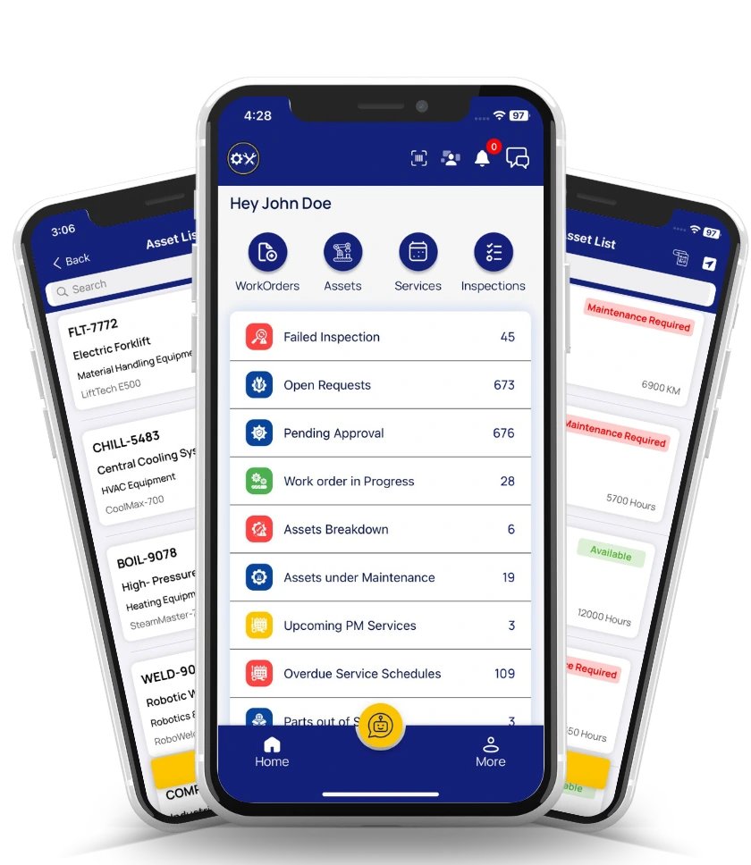
WO lands on the on-shift technician's phone with the trend graph, the recommended diagnostic sequence, PPE requirements, and the last three service photos on that asset attached.
-
04
Diagnostic Executed On-Site
Technician performs the diagnostic — injector cylinder-cut test, coolant flow verification, oil sample pull, battery load test — with results recorded directly in the WO with photo evidence.
-
05
Corrective Action Scheduled
Injector replacement, coolant flush, oil change, battery swap. Scheduled at the next safe window using the P-F lead time the condition monitoring provided — planned, not emergency.
-
06
Root Cause Tagged on Close
Technician closes the WO with a structured root-cause code. The FMEA updates automatically — occurrence rating recalculates, and the ML model refines its future prediction on that failure mode across the fleet.
Built for Diesel Reliability
How Oxmaint Runs the Diesel CBM Programme End to End
-
Multi-Channel Ingest
Vibration + Temp + Oil + Exhaust in One Record
All four channels flow into the same asset record via OPC-UA, Modbus, or direct IIoT gateway. No stitching data across three vendor dashboards to diagnose one fault.
-
Warning / Alarm Bands
ISO 8528-9 Zones Configured per Asset
Per-asset threshold configuration with ISO 8528-9 Zone A/B/C/D vibration bands and calibratable warning/alarm ranges. Baseline auto-captured during first 30 days of operation.
-
Auto Work Orders
Trigger + Diagnostic Procedure Attached
Threshold breach creates a WO with the diagnostic procedure for that specific parameter pre-attached. Technician gets what to do, not just what happened.
-
Oil Analysis Integration
Lab Results in the Asset Record
Lab oil analysis results (Fe, Cu, Cr, glycol, fuel dilution, viscosity) upload directly to the asset record and trend alongside online sensor data — one place for the full oil history.
-
Runtime-Based PM
Overhauls at 6–8K / 12–15K Hrs
Top-end overhaul at 6,000–8,000 hrs and major overhaul at 12,000–15,000 hrs scheduled against actual runtime from the ECU, not calendar. Continuous-service units serviced when they need it.
-
Fleet Reporting
Baseline Deviation, MTBF, Cost per Hour
Fleet dashboard shows each asset's deviation from commissioning baseline, MTBF trend, and cost per operating hour. Reliability director gets the defensible answer when finance asks for CBM ROI.
Measured Outcomes
What Diesel CBM Programmes Actually Deliver
-
2–8 wk
P-F Lead Time on Bearings & Combustion
Properly configured vibration and EGT monitoring reliably detect bearing spalling and cylinder imbalance 2–8 weeks before functional failure — planned intervention window.
-
85%+
Failure Modes Diagnosable
The four-channel stack (vibration + temperature + oil + exhaust) covers 85%+ of diagnosable diesel generator failure modes. The remaining 15% caught by failure-finding tasks on hidden functions.
-
ISO 8528-9
Vibration Zones Configured
Zone A (new machine) through Zone D (unacceptable) severity ranges configured per asset — defensible thresholds aligned to the international standard, not gut feel.
-
$0
Free Forever Plan to Start
Cloud-based, mobile-first. Set up the four-channel monitoring on one generator, prove the sensor-to-work-order loop, and scale to the full fleet when the reliability gain is validated.
Frequently Asked
Diesel Condition Monitoring Questions
Do we need all four channels on an emergency backup generator?
For emergency backup units running <100 hrs/year, the minimum-viable setup is battery voltage monitoring (the #1 cause of start failure), monthly load-bank test with recorded results, and annual oil analysis. Full four-channel monitoring is warranted on prime-power continuous-service units above 1,000 hrs/year. Standby life-safety generators (hospitals, data centers) sit in between — vibration and EGT added to the baseline. Start free and configure the right channel set for your service class today.
Where does the ISO 13373 sensor placement come from?
ISO 13373-1 (Condition monitoring and diagnostics of machines — Vibration condition monitoring — Part 1: General procedures) specifies the minimum sensor configuration for reciprocating machinery including diesel engines: 2–4 accelerometers on the head or block near injectors and support bearings, one acoustic sensor in the compartment, and one rotational reference. ISO 8528-9 provides the vibration severity zones specifically for reciprocating internal combustion engine driven alternating current generating sets.
Why the 30–45° sensor angle from horizontal?
A single sensor mounted at 30–45° from horizontal captures both transverse and vertical vibration components in one measurement. This is the working shortcut when budget or physical access limits you to fewer sensors than the ideal three-axis setup. For Zone D critical assets, dedicated tri-axial accelerometers per bearing are preferred. Book a demo to see the placement layout mapped to your generator model.
How do we prevent alert fatigue?
Two rules. First, use a two-band system (warning + alarm), not a single threshold — warning band means "investigate this shift", alarm band means "schedule shutdown". Second, calibrate thresholds to each specific asset's commissioning baseline over the first 30 days of operation, then re-baseline annually. Fleet-wide static thresholds fire constantly on older units and never fire on newer ones — both are bad.
Is there a free plan to prove condition monitoring on one generator?
Yes. Oxmaint offers a free forever plan — enough to configure the four-channel monitoring stack on one generator, set warning/alarm thresholds, prove the sensor-to-work-order loop, and validate the reliability and cost gain. Cloud-based, mobile-first — no server procurement or infrastructure commitment. Sign up for the free plan and set up your first generator today.
Configure · Baseline · Trend · Act
Condition Monitoring Is Only Real When the Readings Trigger Action.
Four sensor channels, ISO 13373 placement, ISO 8528-9 thresholds, and a closed loop from reading to work order to root cause tag — that is the working diesel generator condition monitoring programme. Oxmaint runs the entire cycle: multi-channel ingest, warning/alarm bands per asset, auto work orders with diagnostic procedures attached, mobile execution, and fleet reporting that gives finance the CBM ROI answer they ask for.





.png)